![[LinuxFocus Image]](../../common/May1998/border-short.jpg)
| News Archives Companies Tips |
RenderManby Carlos Calzada Grau |
Introduction
Instalation
First Steps
Conclusions
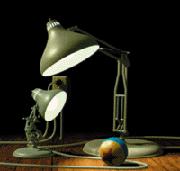
IntroductionWho has never heard of Pixar?, Who has never seen the movie Toy Story?. Pixar Animation Studios is known since a long time ago for its work on computer animations. Luxo Jr. (1986) is the first movie with 3d graphics nominated for an Oscar, it also won more than 20 prizes in international film festivals.
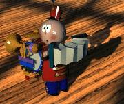
In 1987, Red's Dream won several prizes in the World Animation Festival at Zagreb and in the San Francisco International Film Festival. The first animation that won an Oscar was Tin Toy (1998), Pixar designed a model for the face of a baby defining more than 40 muscles to controled by the animator.
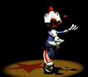

In 1989 they released Knick Knack, this is the story of a snowman that lives inside the crystal ball. The movie was initially produced to be viewed in 3D althout they also released a normal version. Following soon after came a number of succeses like the recent movie Toy Story. This is one of the first long feature films completely produced by computer. In the home page of Pixar many more interesting things can be found, for example the Toy Story 2 film release date is some time in 1999. Pixar developed the interface RenderMan to separate and maintain "modelers" and "renderes" independently . A modeler is a tool used to draw scenes, design animations, etc. The renderer's only purpose is to take the description of the modeler and render it with shadows, lights, textures, etc.. RenderMan lets 3D artists to specify what to render but not how to do it. In other words, a modeler should not be concerned with the rendering step. Similarly a renderer that complies with the standard specifications of RenderMan can use Z-buffer, scan-line, ray-tracing, radiosity or any other method to "draw" the objects, and this step is independent of RenderMan. We can view the interface of RenderMan as a format for the description of scenes in the same way PostScript is a format for the description of pages. This standard is independent of architectures and operating systems. 


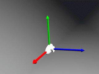
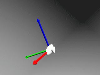
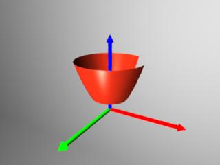
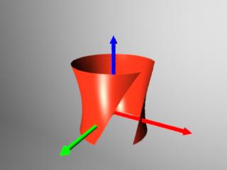
Copyright 1988, 1989, Pixar. All Rights Reserved. RenderMan@ is a registered trademark of Pixar In this article we will attempt to give a small introduction to RenderMan, we will use Blue Moon Rendering Tools, completely written by Larry Gritz. This package is a renderer of free distribution (only binaries and for personal use), there are versions for many systems among which you will find Linux ( in fact this was one of the first implementations), it uses ray-tracing and radiosity and has little to envy to a Photorealistic RenderMan (PRMan), the commercial product of Pixar. At the beginning the system of coordinates for the world and the camera are the same, they are left-hand rule coordinate systems (as Pov-Ray), with the origin at the center of the screen, the X axis to the right, the Y axis upwards and the Z axis going to the inside of the screen. The following figure shows the camera used by default (the X axis is red, Y axis is green and Z axis blue, to see the source code click on the image). A right-hand rule coordinate system is identical but for the Z axis that points in the opposite direction.
In Pov-Ray the system of world coordinates is fixed, meaning one can move the camera through the world and set objects using transformations. In RenderMan the opposite is true, the camera is fixed and what gets transformed to obtained various points of view is the world system of coordinates. All this will become clear when we "desmantle" an example. RenderMan has many primitives, both for object definition as for ligths, etc... Now we will see as an example the format of the most famous cuadrics, although there are others (like bezier patches, polygones, ...).
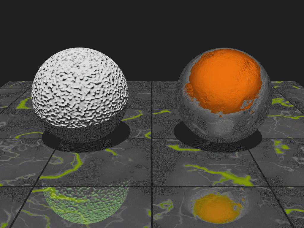
The reader may already notice that the format of some of these primitives is not precisely simple, but taking into account that the file RIB must be supplied by a modeler as output, this format is actually appropriate because of its conciseness and performance. InstallationAs a first step let us go to the home page of Blue Moon Rendering Tools and download the program. At this instance the current version os 2.3.4 and to uncompress it we proceed as usual:rabit:~/$ gzip -d BMRT2.3.6.linux.tar.gz rabit:~/$ tar xvf BMRT2.3.6.linux.tar After uncompressing and unpacking the tar-file we get a new directory named BMRT2.3.6 It contains the executables (in bin/), the examples (in examples/) and the documentation in both PostScript and HTML (under doc/), there is also a README file with additional information about the program. Look within the README file for the installation section, it is simple and should not give trouble to anyone. First StepsLet us become familiar with RenderMan's specification by examining a typical example (../../common/May1998/disptest.rib). The image is generated by the command rendrib -v ../../common/May1998/disptest.rib (click the image to view it in 1024x768 resolution and with anti-aliasing 2x2). This is one of the many samples that can be found in the examples/ directory of BMRT (Blue Moon Rendering Tools) and as the reader can appreciate the file that generated it is not very long (when writing animations you will see the file growing considerably).
There are several executables under bin/: rendrib, rendribv and rgl. Rendrib is the renderizer properly speaking, rendribv is similar but it renders objects in wire mode, only with lines; finally rgl renders using polygons. The last three renderers are used to preview positions, animations, etc.. and the final rendering must always be done with rendrib. The format of the file RIB (Renderman Interface ByteStream) is very simple, although not necessarely less powerful. They are saved as plain text files (exactly like Pov-Ray). A well-writen RIB file contains the following:
The graphical state contains all the information needed to render a primitive. It is divided in two parts: a global that remains constant from primitive to primitive and a current state that changes with primitives. The parameters of the global state are known as options and the current states are named attributes To better understand options and attributes, and to have an idea
of how to specify scenes with RenderMan, let us review the preview example
line by line. This would be a good tutorial on what can be done and
how to get it done.
Comments can be included in the file using the # symbol, see line 1 and from lines 4 to 12. A # symbol may appear in any place of the file and they occupy a full line (like // comments in C++ ). Comments should be used when editing these files manually because they help us understand the inner workings of the scene. Line 2 shows an example of the version directive. It merely declares the version of interface being used (3.03); the most recent version is 3.1 released september 1989 (yes 1989, it is not a mistake), although there are revisions of May 1995. The directives searchpath and shader on line 14 defines the path for the "shaders", these are objects that inform the renderer how to reder a given object (as a plastic, transparent, etc..), this is one of the features that makes the interface very powerful because the textures of an object behave as Plug-Ins, therefore it is easy to implement new textures, effects,... not having to wait for a more powerful release of the renderer. Usually there is an environment variable (SHADER) that indicates the location of these files, therefore it is not often necessary to declare the path explicitly. The Display option appears on line 15. It declares the output filename as "balls2.tiff" and its type as "file" "rgb", that ism an RGB file. In line 16 we define the resolution for rendering (size of the image) through the Display option. The resolution of our example is 400x300, the -1 defines the aspect ratio of the pixel (actually it should be +1, I am not sure why they used -1 here). Next comes the horizontal and vertical sampling for every pixel, i. e., the number of rays launched to render a pixel. An stament PixelSamples 2 2 translates into 4 rays launched per pixel, prividing a great quality for the image (this is the anti-aliasing), but unfortunately a larger time for rendering. In our case, a sampling of 1 x 1 = 1 provides a faster rendering time but only one ray per pixel. Line 19 declares the integer variable prmanspecular , actually prmanspecular gets defined as a token and when the renderer finds this token it will take as an integer whatever number follows.
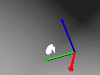
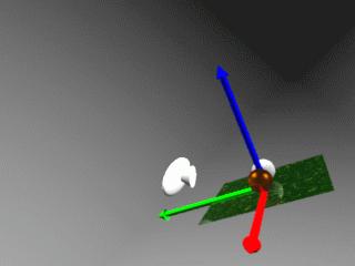
Lines 22 and 23 then defined the position of the camera. First we write a translation followed by a rotation, but since all transformations are performed through a stack the first transformation to be applied is the last one in, rotation followed by a translation (in this case the transformations get executed once renderman finds the statement WorldBegin ). In this example the system rotates -100 degrees around the X axis (to rotate around the Y axis one would have written Rotate 45 0 1 0), next it is translated -0.55 units along the Y axis and 8 units along the Z axis. Please take into account that what gets transformed (rotated and translated) is not really the camera but the center of world coordinates (translator's note: OpenGL uses exactly the scheme for transformations). The following figures show different stages during the two transformations.
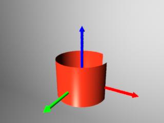
After the previous preliminaries definitions comes the scene itself. Any scene (a declaration of lighting, objects, etc..) always begins with WorldBegin and ends with WorldEnd (lines 26 and 64 respectively). The first few lines in the scene of our example declares the lightning (lines 28 to 32); every light has a number and in theory they must be distinct, the first one is the ambient light and it has 0.02 intensity. After lighting the variable shadows is declared as a character string and then the lighting option for casting shadows is activated. Line 32 adds a light source of the type distantlight (a light source infinitely far a way like the sun) using number 1 again; as mentioned before this light source should be different (say 2), it still works becuase BMRT appears to ignore the light numbering, however to keep compatibility (for example with Pixar's PRMan) we should be stricter with the interface. The intensity of the secound source of light is identical to the first one (these are common attributes) and the direction vector defined by the fields from and to, send the rays in parallel, as if it was a distant source. A partir de aquí tenemos los tres objetos que forman la escena, cada objeto está encerrado en un par AttributeBegin, AttributeEnd, ya que cada uno tiene sus propias características, tanto de posición como de apariencia, si lo único que cambiaramos de un objeto a otro fuera su posición, podríamos declarar la textura fuera y a continuación definir los objetos con TransformBegin y TransformEnd. El primer objeto (lineas 34 a 42) es un parche, los parches pueden ser: uniformes o no-uniformes, racionales o no-racionales y bilineares o bicúbicos, con esto se consiguen parches Bezier, BSplines etc. (un libro sobre gráficos por ordenador ayudaría bastante a comprender esto). En este caso tenemos un parche bilinear con cuatro puntos, estos se definen con "P" y luego se ponen las coordenadas (x,y,z) de los puntos que queramos. La textura del objeto se consigue con la directiva Surface, el primer argumento es un fichero shader, las siguientes son específicas de cada shader. En la imagen siguiente tenemos como queda la escena al añadir este cuadrado. 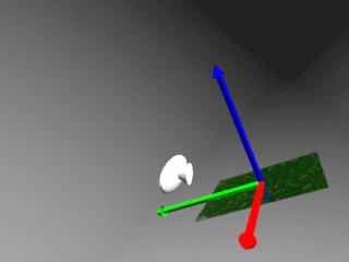
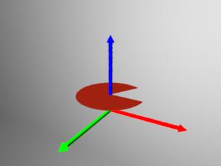
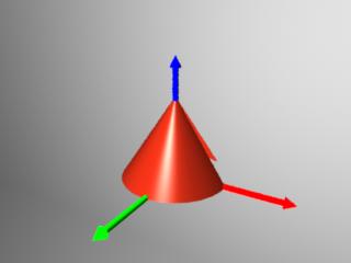
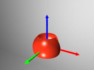
Lines 44 to 52 define several objects within the scence: an sphere (line 51) whose color is specified with the directive Color [R G B]. This sphere is translated and given a surface type, matte in this present case. Next comes the most important feature of BMRT, the displacement shaders. They are analogous to the bump-maps of Pov-Ray except that under BMRT these "bumps" are not simulated but they are real. The final effect is that the surface and borders of the sphere appear rough. shaders for displacement are similar to those for textures, always go declare as a name for a particular shader followed by its parameters. The specification of the sphere is a bit strange; first goes the radius, then zmin and zmax clip the sphere along the z-axs (for example values -1 and 1 would leave the sphere intact while values 0 and 1 would cut it in half), the last value are the degrees covered by the sphere (360 is the whole sphere, 180 half, etc..). Here is an image of the first sphere in position: 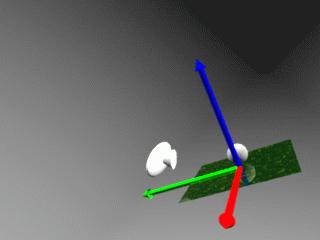
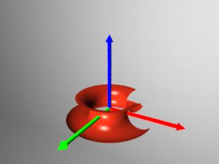
The following object is similar to the first one except for different texture and displacement characteristics, therefore I will not repeat the same explanation here, and let us simply run the code and see what we get:
This completes the file. At this point it should be clear that the development of scenes is not complex, but a complicated scene or an animation can make the file very complex. To avoid this, is enough to use a modeler that supports RenderMan (any modeler of estime exports RIB files) or alternatively to program the animacion in C. In the distribution of BMRT come the include directory and the necessary libraries. They contain functions that send to standard output the RIB file. Both methods are completely indentical: WorldBegin in a RIB file corresponds to RiWorldBegin() in a C program (to learn more about it read RenderMan for Poets which is located in the doc/ directory). ConclusionsRenderMan interface is very powerful and in fact Toy Story was made using it (with a modeler called marionet). In www.toystory.com there are some articles about the movie and a few other things. The specification of the interface can be found at giga.cps.unizar.es. Besides the specification there is manual for PRMan (Pixar's the renderer ) also some examples.In the next article we will model a little object, it will be done in C so that it can be animated easier later on and also in order to become familiar with the library. The small object for the animation could be the Linux penguin or maybe Bill Gates (or both and we make the penguin fry the other.. :) | ||||||||||||||
Translated by Miguel Angel Sepúlveda
- Other articles in this volume: MindsEye: 3D Modeling, Pov-Ray: Basic Notions
- Other articles in previous volumes: POV-Ray: First Steps
- Home page of BMRT http://www.seas.gwu.edu/student/gritz/bmrt.html
- RenderMan Repository http://rmr.spinne.com/
- Pixar http://www.pixar.com/
- GIGA (Grupo de Informatica Grafica Avanzada) http://giga.cps.unizar.es/prman/
- Home Page of Toy Story http://www.toystory.com/
- RenderMan course in PDF: http://rmr.spinne.com/KessonPDF/index.html
This web site is maintained by Miguel A Sepulveda.